- 您现在的位置:买卖IC网 > Sheet目录3851 > PIC16F88-I/ML (Microchip Technology)IC MCU FLASH 4KX14 EEPROM 28QFN
104
8008H–AVR–04/11
ATtiny48/88
inverted. The dual-slope operation has lower maximum operation frequency than single slope
operation. However, due to the symmetric feature of the dual-slope PWM modes, these modes
are preferred for motor control applications.
The PWM resolution for the phase correct PWM mode can be fixed to 8-, 9-, or 10-bit, or defined
by either ICR1 or OCR1A. The minimum resolution allowed is 2-bit (ICR1 or OCR1A set to
0x0003), and the maximum resolution is 16-bit (ICR1 or OCR1A set to MAX). The PWM resolu-
tion in bits can be calculated by using the following equation:
In phase correct PWM mode the counter is incremented until the counter value matches either
one of the fixed values 0x00FF, 0x01FF, or 0x03FF (WGM1[3:0] = 1, 2, or 3), the value in ICR1
(WGM1[3:0] = 10), or the value in OCR1A (WGM1[3:0] = 11). The counter has then reached the
TOP and changes the count direction. The TCNT1 value will be equal to TOP for one timer clock
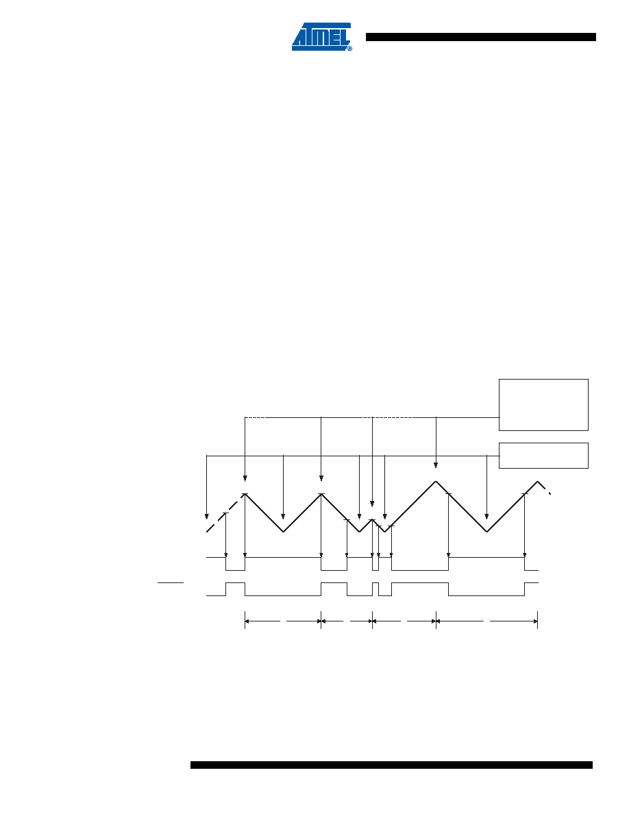
cycle. The timing diagram for the phase correct PWM mode is shown on Figure 12-8. The figure
shows phase correct PWM mode when OCR1A or ICR1 is used to define TOP. The TCNT1
value is in the timing diagram shown as a histogram for illustrating the dual-slope operation. The
diagram includes non-inverted and inverted PWM outputs. The small horizontal line marks on
the TCNT1 slopes represent compare matches between OCR1x and TCNT1. The OC1x Inter-
rupt Flag will be set when a compare match occurs.
Figure 12-8. Phase Correct PWM Mode, Timing Diagram
The Timer/Counter Overflow Flag (TOV1) is set each time the counter reaches BOTTOM. When
either OCR1A or ICR1 is used for defining the TOP value, the OC1A or ICF1 Flag is set accord-
ingly at the same timer clock cycle as the OCR1x Registers are updated with the double buffer
value (at TOP). The Interrupt Flags can be used to generate an interrupt each time the counter
reaches the TOP or BOTTOM value.
RPCPWM
TOP 1
+
()
log
2
()
log
-----------------------------------
=
OCRnx/TOPUpdate and
OCnA Interrupt Flag Set
or ICFn Interrupt Flag Set
(Interrupt on TOP)
1
2
3
4
TOVn Interrupt Flag Set
(Interrupt on Bottom)
TCNTn
Period
OCnx
(COMnx[1:0] = 2)
(COMnx[1:0] = 3)
发布紧急采购,3分钟左右您将得到回复。
相关PDF资料
PIC18F26J53-I/ML
IC PIC MCU 64KB FLASH 28QFN
PIC18F46K80-I/ML
MCU PIC 64KB FLASH 44QFN
PIC32MX130F064D-I/TL
IC MCU 32BIT 64KB FLASH 44-VTLA
PIC32MX130F064D-I/ML
IC MCU 32BIT 64KB FLASH 44-QFN
PIC18LF46K80-I/ML
MCU PIC ECAN 64KB FLASH 44QFN
AT89S51-24JI
IC 8051 MCU 4K FLASH 44PLCC
AT89S51-24JC
IC 8051 MCU 4K FLASH 44PLCC
AT89S51-24AI
IC 8051 MCU 4K FLASH 44TQFP
相关代理商/技术参数
PIC16F88-I/ML
制造商:Microchip Technology Inc 功能描述:8BIT FLASH MCU SMD 16F88 QFN-28
PIC16F88-I/P
功能描述:8位微控制器 -MCU 7KB 368 RAM 16 I/O RoHS:否 制造商:Silicon Labs 核心:8051 处理器系列:C8051F39x 数据总线宽度:8 bit 最大时钟频率:50 MHz 程序存储器大小:16 KB 数据 RAM 大小:1 KB 片上 ADC:Yes 工作电源电压:1.8 V to 3.6 V 工作温度范围:- 40 C to + 105 C 封装 / 箱体:QFN-20 安装风格:SMD/SMT
PIC16F88-I/P
制造商:Microchip Technology Inc 功能描述:IC 8BIT FLASH MCU 16F88 DIP18
PIC16F88-I/SL
制造商:Microchip Technology Inc 功能描述:
PIC16F88-I/SO
功能描述:8位微控制器 -MCU 7KB 368 RAM 16 I/O RoHS:否 制造商:Silicon Labs 核心:8051 处理器系列:C8051F39x 数据总线宽度:8 bit 最大时钟频率:50 MHz 程序存储器大小:16 KB 数据 RAM 大小:1 KB 片上 ADC:Yes 工作电源电压:1.8 V to 3.6 V 工作温度范围:- 40 C to + 105 C 封装 / 箱体:QFN-20 安装风格:SMD/SMT
PIC16F88-I/SO
制造商:Microchip Technology Inc 功能描述:8BIT FLASH MCU SMD 16F88 SOIC18
PIC16F88-I/SOG
功能描述:8位微控制器 -MCU 7KB 368 RAM 16 I/O Lead Free Package RoHS:否 制造商:Silicon Labs 核心:8051 处理器系列:C8051F39x 数据总线宽度:8 bit 最大时钟频率:50 MHz 程序存储器大小:16 KB 数据 RAM 大小:1 KB 片上 ADC:Yes 工作电源电压:1.8 V to 3.6 V 工作温度范围:- 40 C to + 105 C 封装 / 箱体:QFN-20 安装风格:SMD/SMT
PIC16F88-I/SS
功能描述:8位微控制器 -MCU 7KB 368 RAM 16 I/O RoHS:否 制造商:Silicon Labs 核心:8051 处理器系列:C8051F39x 数据总线宽度:8 bit 最大时钟频率:50 MHz 程序存储器大小:16 KB 数据 RAM 大小:1 KB 片上 ADC:Yes 工作电源电压:1.8 V to 3.6 V 工作温度范围:- 40 C to + 105 C 封装 / 箱体:QFN-20 安装风格:SMD/SMT